
Stabilize The Duty
Check airflow and static pressure, then remove avoidable pressure loss so the fan does not run faster than the duty requires.
Noise And System Diagnosis
If an industrial exhaust fan is too loud, identify whether the objection is aerodynamic sound, mechanical vibration, duct/system noise or another source before selecting a silencer.

Direct Answer
Map the source first, then correct the operating point, mechanical condition, system effect or structure-borne path before adding a silencer.
A steady broadband rush, a tonal rattle and a vibrating wall panel are different problems. Record fan speed, airflow, static pressure, measurement position, weighting and background level so a supplier can compare the same operating condition.
A supplier's dB(A) line is useful for screening, but it is not a field guarantee unless the test method, measurement position, room, speed, airflow and pressure are also known.
Engineering scope and sources reviewed 6 October 2026 · Project conditions still govern final selection
Decision Framework
Choose the lever that matches the source; a quieter component cannot repair a wrong air path or a failing bearing.
Check airflow and static pressure, then remove avoidable pressure loss so the fan does not run faster than the duty requires.
Inspect imbalance, bearings, rubbing parts, loose guards, mounts and fasteners before treating airborne sound.
Review elbows, transitions, clearances, dampers, screens and discharge interaction with walls or roofs.
If the duct, support or panel carries vibration, select connectors and isolators for the actual weight, speed and support.
Confirm insertion loss, airflow, pressure drop, access and cleaning; do not trade an unresolved noise complaint for lost airflow.
Field Inputs
Every candidate should be compared on the same duty and measurement basis; a lone dB(A) number is not a ranking.
| Field input | Record | Why it governs |
|---|---|---|
| Observed signature | Broadband rush, tonal hum, rattle, panel or duct response | Points the investigation toward aerodynamic, mechanical, system or structure-borne noise. |
| Operating point | Fan model, speed/control setting, airflow, static pressure and damper position | Noise changes with speed and duty; different points cannot be compared as if identical. |
| Measurement basis | Sound power or pressure, dB weighting, distance, room/free-field condition and background | Defines what the number means and whether two readings are comparable. |
| System path | Inlet/outlet geometry, elbows, transitions, screens, discharge and nearby walls | System effect and turbulence can dominate an otherwise reasonable fan selection. |
| Mechanical condition | Balance, bearings, rubbing, guards, mounts, supports and fasteners | A silencer does not repair a mechanical fault or loose structure. |
| Proposed treatment | Silencer side, insertion loss data, pressure drop, access, cleaning and support | Confirms that the fix fits the duty and can be maintained. |
Boundary: AMCA test standards define methods and calculations; they do not turn a catalog reference value into a guaranteed installed-room result. Final selection still depends on the project duty, adopted code and qualified review.
Practical Sequence
Visual Check
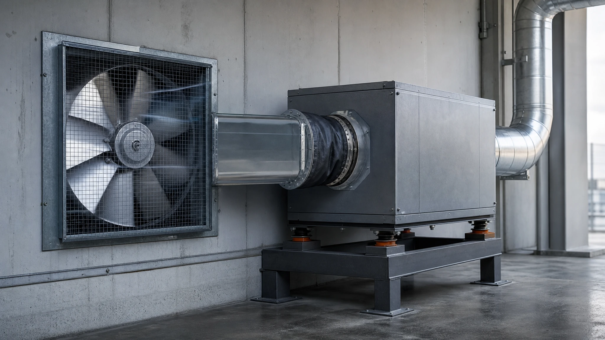
These independent views show the physical relationship behind the recommendation. They are not a substitute for project measurements or a supplier selection.
Connected Decisions
These links continue the same project workflow rather than sending the reader to loosely related content.
Confirm airflow and pressure before changing the fan or adding resistance.
Check mechanical causes before specifying acoustic treatment.
Map openings, source capture, make-up air and system interaction.
Check balance and pressure interaction when exhaust changes.
Review available configurations, then request a project-specific comparison.
Questions Buyers Actually Ask
No. A larger fan may meet the duty at a lower speed, but the installed result still depends on fan design, pressure, system effect, room and measurement basis.
Not safely without the test method, distance, room or free-field condition, speed and duty. The same number can describe different quantities.
No. Attenuation depends on frequency, insertion loss, airflow, pressure drop, leakage and installation geometry. Obtain a project-specific selection and verify the result.
No. They are catalog reference values. The current catalog does not expose the complete test setup needed for an apples-to-apples field comparison; final model and duty must be confirmed in the quotation and project review.
Record both when possible, plus the inlet, discharge, support and duct. The fan point helps identify the source; the occupied point shows the project impact and the path between them.
Often, but only if the required airflow and static pressure remain satisfied. Verify the operating point after any control change and compare readings at the same duty.
Source Boundary
Sources define methods and safety boundaries. They do not certify a proposed AirMoveX model or replace the adopted code, OEM instructions or a qualified project designer.
AMCA
Defines a reverberation-room method for airborne sound emission from fans and distinguishes the scope from vibration measurement.
Open sourceAMCA
Provides calculation methods for fan sound ratings from laboratory test data when an applicable test standard exists.
Open sourceAMCA
Describes a laboratory sound-intensity method for determining octave-band sound power levels.
Open sourceAMCA
Use the current edition and adopted project requirements when defining the test and reporting basis.
Open sourceProject Review
Share the fan duty, system sketch, installation position, room use, nearest occupied or property boundary, operating schedule and current sound/vibration observations. AirMoveX can review candidate equipment inside that project boundary.
Start With The Space
Share the dimensions, installation height, available power and operating problem. We will prepare a practical starting configuration.